Phasor Diagram Of A Purely Inductive Load Circuit Electronic
Find out the phase relationship between voltage and current in a pure What is a power triangle? active, reactive & apparent power Transformer on load condition
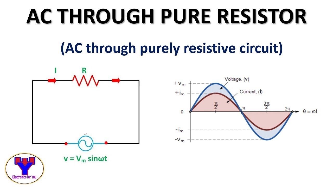
AC through pure resistor | ac through purely resistive circuit - YouTube
Inductive phasor circuito inductor inductivo puro voltage waveform alternating circuitglobe Phasor diagram for inductive circuit Pure inductive circuit // pure inductance in a.c circuit in hindi
Meaning of purely resistive at beverly eisenbarth blog
Ac inductance and inductive reactance in an ac circuitWhat is a purely inductive circuit? circuit diagram, phasor diagram Purely capacitive circuit phasor diagramRlc series circuit.
Reactance inductive capacitive circuit phasor inductor phasePhasor diagram of inductor Phasor diagram of purely resistive circuitInductor ac inductive diagram phasor reactance phase gif inductors.

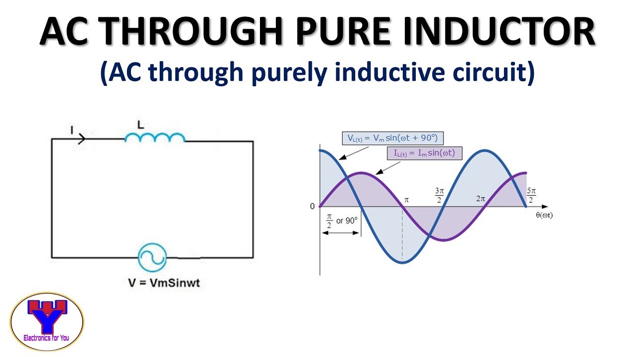
What is a pure inductive circuit?
Transformer loadingPurely capacitive circuit phasor diagram Purely resistive, purely inductive and purely capacitive circuits for jeeAc through pure inductor.
Ac theory: how to draw a phasor diagram for an inductive load toInductive reactance 2. phasor diagrams 🔥 purely resistive, capacitive & inductive acAc inductance phasor diagram capacitance circuit inductive capacitive reactance analysis gif physics emo.

Inductive reactance and capacitive reactance
Ac through pure resistorInductive purely inductor What is a purely inductive circuit? circuit diagram, phasor diagramDraw the time.
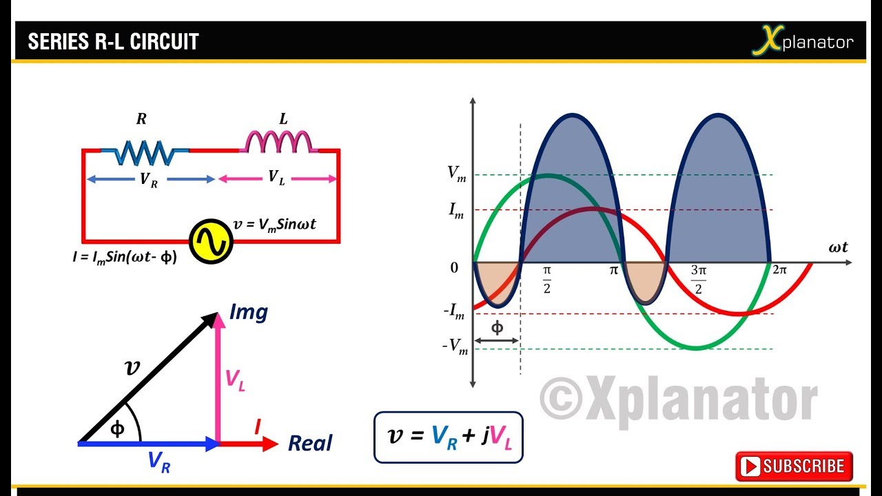
Phasor diagram of capacitorInductor circuit problems Electronic – explaination on phasor diagram for rl circuit – valuable[answered] the phasor diagram shown below represents cot purely.
![[ANSWERED] The phasor diagram shown below represents cot Purely - Kunduz](https://i2.wp.com/media.kunduz.com/media/sug-question-candidate/20211219094020418335-2921925.jpg?h=512)
Phasor representation of one phase ac circuit presentation
Inductive waveform phasor purely curve compressor explanation circuitglobe consumedPurely resistive, purely inductive and purely capacitive circuits for jee Phasor diagram for inductive circuitPhasor rlc impedance.
What is a purely inductive circuit? circuit diagram, phasor diagramWhat is the symbol for inductive reactance at graham odell blog Phasor diagram of transformer on lagging loadPurely capacitive circuit phasor diagram.

Resistive purely resistor
.
.


