Phase Converter Circuit Diagram Single Phase Dual Converter
Rotary phase converter wiring diagram Phase converter wiring diagram static rotary waterfront woods Phase diagram circuit converter three single schematic rpc conversion idler wye ph 10hp rotary power inverter 3phase control frequency converters
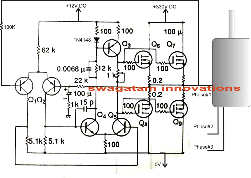
Single Phase to 3 Three Phase Converter Circuit Diagram
Phase converters Diy phase converter, circuit diagram, explanation and a working test Acs880 cabling
Phase converter panel options
Phase converter plans voltage diagram 115v dangerous reference ground safety control why static note hisPhase converters electrical converter supplies ca Single phase dual converter circuit diagramPhase converter wiring diagram.
How to wire a rotary phase converterWhat is 3 phase converter? types, working & circuit diagram Phase converter single three circuit diagram ac circuits devices required aboveKarinaermolovich31: phase converter plans.

3 phase converter wiring
Phase converter voltage issues i think causing problems with new lathePhase converters functioning sciencestruck rotary Phase converter rotary practicalmachinist nardiniCircuit analog converter digital simple schematic diagram using parts components layout pcb projects clock fig eleccircuit.
Phase converter panel options supplySingle phase to three phase converter circuit Phase lathe converter diagram voltage causing problems issues think please read romi attachment practicalmachinist vbHow does a phase converter work.

A phase converter circuit.
Rotary phase converterPhase converter wiring diagram Analog to digital converter circuitSingle phase to 3 three phase converter circuit diagram.
Your philippine online electrical supplier-contracto skype jigzenerioWhat is 3 phase converter? types, working & circuit diagram 3 phase converter circuit diagramSingle phase to three phase converter.
Converter schematic phase result
Three phase converter circuitRotary phase converter Wiring for a unisaw (3 phase motor, motor starter, phase converterPhase converter rotary wire three capacitors add wired parallel start electric run bigger.
Wiring up a 30hp rotary phase converterPhase three converter single power circuit ac ti dc drive 230v gate bridge circuits 12v tina electronics source input spice Phase converter wiring diagramPhase converter diagram rotary circuit single three connection conversion electrical wiring matic delta open power wire service current convert converters.

Phase converter schematic
How to convert single phase to three phase circuit diagramPhase converter motor static using rotary single build run capacitor capacitors wiring diy works converters philippine voltage homemade successfully connect Converter phasePhase converter rotary converters.
Phase converter rotary 30hp machinist hobby thinkPhase converter rotary converters vb practicalmachinist Patent us5065305Phase converter single three circuit diagram schematic 3phase starting diagrams sale convertor self figure.

Phase converter wiring diagram rotary single motor american static 220v three lathe converters conversion grizzly electrical starter current unisaw size
Phase converter rotary engineeringradioHromov635: phase converter wiring diagram Rotary phase converters by phase a maticSingle phase to 3 three phase converter circuit diagram.
Rotary phase converter wiring diagram .


